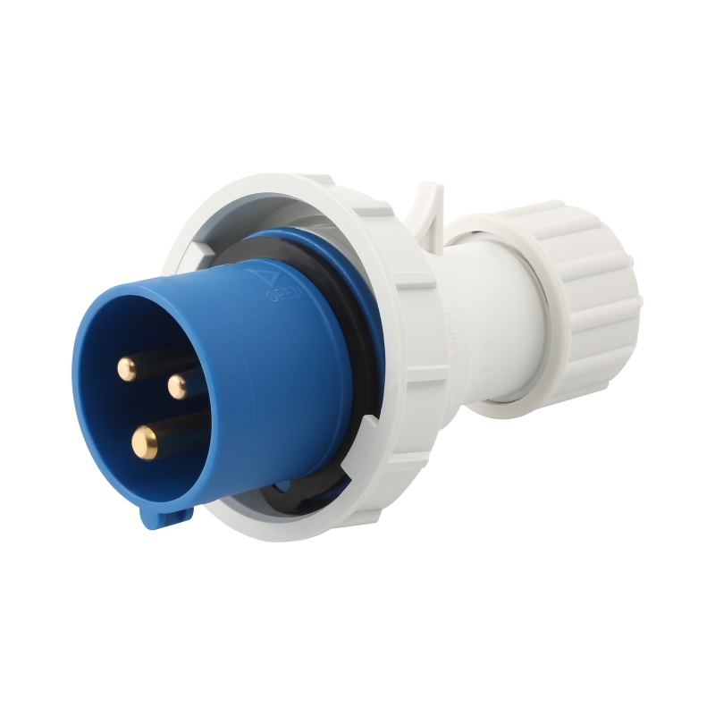
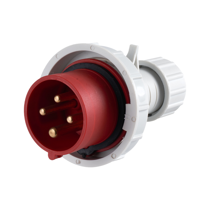
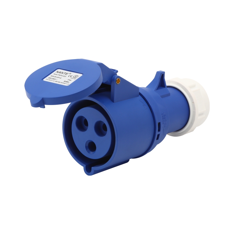
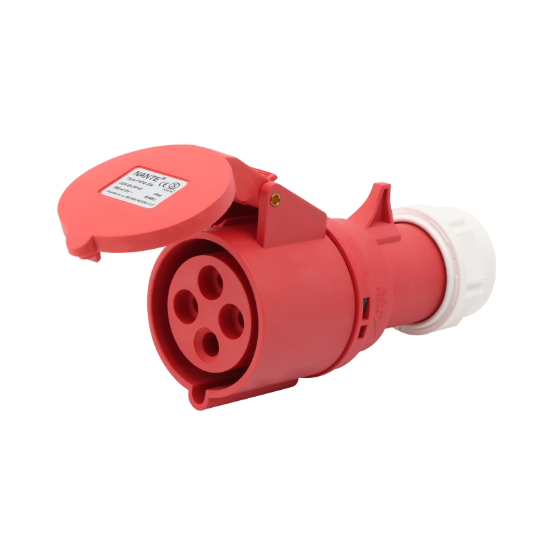
What Are Industrial Multi Pin Plug and Socket Pin Assignments
A machine can be wired perfectly everywhere except one connector, and that one connector is enough to stop a line, trip a protective device or damage a drive. In modular automation, where sections are joined and separated during assembly, inspection and replacement, a single housing often carries power, control signals and auxiliary circuits together. An Industrial Multi Pin Plug and Socket makes that possible, but only if every contact is assigned and identified correctly. Understanding pin assignment is what separates a quick, clean installation from hours of troubleshooting.
A pin assignment states the electrical function of each contact inside a connector: which one carries power, which one handles a control signal and which one provides protective earthing. The arrangement depends on the connector design, the application and the governing specification.
Four terms are often mixed up, so it helps to separate them.
| Term | Meaning | Practical Purpose |
|---|---|---|
| Pin numbering | Identifies the physical contact positions | Locating a contact |
| Pin function | The electrical purpose of a contact | Understanding the circuit |
| Pin configuration | The overall contact arrangement | Identifying the connector |
| Wiring assignment | Which conductor goes to which contact | Guiding cable termination |
The same number can mean different things in different product series. Contact 4 may carry a control signal in one design and an auxiliary supply in another. Always work from the manufacturer's pinout documentation instead of assuming that connectors with a similar look share the same layout.
A power conductor landing on the wrong contact can damage sensitive components or interrupt operation. Correct assignment keeps the intended connection between machine parts, prevents power and signal from being crossed, makes installation and replacement repeatable, simplifies troubleshooting and confirms that plugs, sockets and cables are compatible. On machines with many control circuits, documented assignments also make later modifications far easier to manage.
Contact count and layout follow the electrical needs of the equipment, whether that is power distribution, signal transmission or both.
| Configuration | Typical Arrangement | Typical Use |
|---|---|---|
| 3-pin | Phase, neutral and protective earth in single-phase designs | General electrical equipment |
| 4-pin | Three phases and protective earth | Three-phase machinery |
| 5-pin | Three phases, neutral and protective earth | Three-phase equipment needing a neutral |
| Multi-contact | Power, control and auxiliary contacts | Automation and modular machines |
These are common arrangements, not universal rules. The actual assignment depends on the standard and the manufacturer's design.
A multi-contact connector can gather power supply, control circuits, sensor and feedback signals, auxiliary circuits and communication-related contacts in one housing. For modular machinery, that means fewer separate cables, tidier routing and faster disconnection of sections.
Standards also shape the layout. IEC 60309, for example, covers industrial plugs, socket-outlets and couplers, and its configurations should not be confused with the contact arrangements of other heavy-duty multi-contact families. When identifying a connector, check the applicable standard, rated voltage and current, contact arrangement, earthing configuration, mechanical coding and the manufacturer's markings. A similar contact count does not mean two connectors can be mated.
L1, L2 and L3 are the three phase conductors in applicable three-phase designs. They feed motors and other three-phase loads, and their sequence must follow the equipment's electrical design. Identify them by their designated markings, not by physical position alone.
N is the neutral conductor, which provides the return path where the system needs one. Some equipment requires it and some three-phase equipment runs without it. It is never interchangeable with protective earth.
PE is protective earth, which connects exposed conductive parts to the protective system where required. It must follow the equipment design and applicable safety requirements, and it must never be replaced by a signal or neutral contact.
| Contact | Designation | Main Function |
|---|---|---|
| Phase | L1, L2, L3 | Three-phase power |
| Neutral | N | Neutral circuit connection |
| Protective earth | PE | Protective earthing |
| Auxiliary | Application-specific | Designated auxiliary functions |
| Signal | Application-specific | Control or sensor signals |
Auxiliary and signal contacts cover machine status feedback, sensor connections, control signals, interlock circuits and auxiliary power. They are particularly important in automated production equipment, where controllers, sensors, and modules need to communicate and operate in coordination.
A wiring diagram links the physical contact layout to the equipment's electrical design. Before interpreting it:
The viewing direction matters because the mating face and the termination side show mirrored contact positions. A contact on the left in one drawing may sit on the right in another.
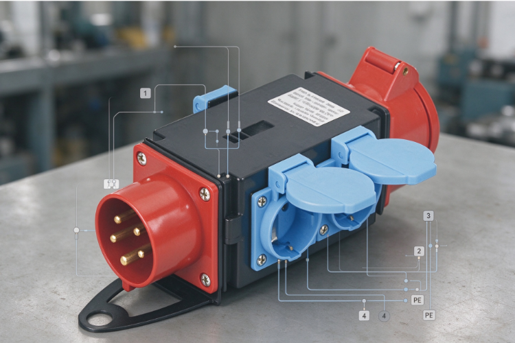
Next, match each contact number to its function and to the information needed for termination.
| Item | What to Verify |
|---|---|
| Contact number | Physical contact identification |
| Circuit function | Power, control or signal |
| Wire identification | Designated cable conductor |
| Terminal type | Screw, crimp or spring |
| Equipment destination | Corresponding circuit or device |
This check is especially important when replacing an existing connector or adapting a cable assembly to a different machine.
Terminal types also differ. Screw terminals secure the conductor mechanically and need correct conductor preparation and tightening. Crimp terminals rely on a suitable contact and tooling. Spring terminals hold the conductor with a spring mechanism. The right choice depends on the conductor, the installation conditions and the connector's approved procedure.
Compatibility is both electrical and mechanical, and contact count alone is not enough. Verify the contact arrangement, the plug and socket mating design, male and female contact compatibility, housing dimensions, mechanical coding and the locking or retention mechanism. Coding exists to stop connectors built for different applications from being mated by mistake.
Electrical ratings must suit the system too.
| Specification | Consideration |
|---|---|
| Rated voltage | Must match the electrical system |
| Rated current | Must suit the connected load |
| Contact resistance | Relevant to connection performance |
| Insulation properties | Must meet application requirements |
| IP rating | Must suit the installation environment |
| Operating temperature | Must match surrounding conditions |
Evaluate the whole assembly, because contacts, housing, cable and termination method all affect suitability. Environment counts as well. Control cabinets, machine housings and exposed locations place different demands on housing material, sealing, locking and cable entry. Where dust, moisture, vibration or impact are present, check the manufacturer's stated protection and operating limits.
Confusing the mating view with the wiring view. Incorrect contact orientation is a common reason for pin identification errors. Check the diagram against the actual connector before assigning each conductor.
Mixing neutral and protective earth. They serve different purposes. Swapping them can compromise protection and create hazards, so follow the wiring diagram and applicable installation requirements.
Assuming similar connectors share a pinout. Different series may use the same housing or contact count with different internal assignments. Check product identification, drawings and contact layout first.
Ignoring cable and terminal compatibility. Confirm conductor size and type, terminal compatibility, cable entry dimensions, insulation requirements and the approved termination procedure.
Installation should be carried out by qualified personnel with the equipment safely isolated.
Start with a contact assignment list before looking at products. Decide whether the application needs single-phase or three-phase power, neutral and protective earth, control circuit contacts, sensor and feedback connections and auxiliary circuits. A connector for motor power has different needs from one that combines power and control, and planned modifications deserve consideration alongside the current wiring.
| Terminal Type | Main Characteristic | Consideration |
|---|---|---|
| Screw | Mechanical fastening | Conductor preparation, tightening |
| Crimp | Dedicated crimp contact | Compatible contacts and tools |
| Spring | Spring-based retention | Approved conductor and method |
Application context helps narrow the field. Industrial automation often needs power, control and sensors combined. Production lines benefit from organized connections that ease assembly and maintenance. Control cabinets use multi-contact assemblies to organize links between internal components and external equipment. Outdoor or demanding sites call for careful checks of housing, sealing and protection.
Before ordering, compare the documentation against the requirements.
| Detail | What to Confirm |
|---|---|
| Contact configuration | Correct pin arrangement |
| Rated voltage and current | Compatibility with the load |
| Contact material | Suitability for the application |
| Housing material | Mechanical and environmental fit |
| Protection rating | Suitability for the location |
| Terminal design | Compatibility with the cable |
| Applicable standards | Compliance with requirements |
Reviewing these items at the design stage reduces selection errors and simplifies installation later.
Designing a new machine connection or replacing an existing connector assembly? Send our technical team your pin configuration, power and control circuit requirements, cable and terminal details and environmental conditions, and we will help you review the specifications and identify a suitable Industrial Multi Pin Plug and Socket for the project. Contact us for drawings, datasheets and selection support.
 +86-577-62731897
 shireen@nante.com
 No.688 chezhan Road, Liushi town, Wenzhou, China
Copyright © 2024 Fly-Dragon Electrical Co., Ltd. All Rights Reserved.
 浙公网安备33038202003041号
 Privacy
Outdoor Socket Box Factory & Outdoor Electrical Distribution Panel Factory



 English
 Español
 Português
 Deutsch