What Is Inside a Distribution Board and What Does Each Part Do
Pop the cover off a distribution board and most people expect a tangle of wires. What they actually find, on a properly built board, is closer to a small, organized electrical system—DIN rails holding rows of breakers, busbars running cleanly across the back, neutral and earth bars grouped at defined points, everything labeled and traceable back to a specific circuit. The gap between "a box full of wires" and "an organized distribution system" is exactly where good internal design earns its value.
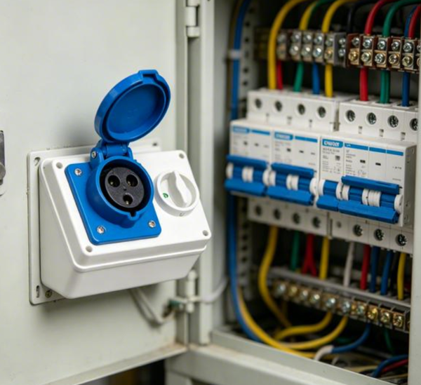
That distinction matters more than it looks like from the outside. A distribution board isn't just a junction point where cables happen to converge—it's the piece of an electrical installation that takes a single incoming supply and splits it into individually protected, individually switchable circuits. Every part inside has a specific job: some handle switching, some handle protection, some handle organization, and how well those jobs interact determines whether the board is a genuine asset during maintenance or a liability waiting to cause a delay during the next fault-finding job.
As buildings and facilities keep adding electrical load—more circuits, more sensitive equipment, sometimes surge-prone electronics—the internal arrangement of a distribution board has become a bigger consideration than it used to, not just for the electrician wiring it initially, but for whoever has to open that same board five years later and figure out what's actually going on inside it.
So what's actually inside, and what does each part genuinely do?
At its core, a distribution board takes one incoming supply—single-phase or three-phase, depending on the installation—and divides it into multiple protected outgoing circuits, each sized and rated for whatever it's feeding: lighting circuits, socket outlets, fixed equipment, HVAC loads, or specialized circuits for anything drawing significant current.
Splitting the load this way isn't just administrative tidiness. It means a fault on one circuit—say, a socket circuit tripping due to an overload—doesn't take down lighting or other unrelated circuits sharing the same board. That's the practical payoff of circuit separation, and it's a core requirement under most electrical installation standards, including IEC 61439, which governs the construction and verification of low-voltage switchgear and distribution assemblies.
The enclosure itself does double duty—housing the internal components while also providing a defined barrier against accidental contact with live parts, dust, and moisture ingress depending on its IP rating.
Scale changes the internal complexity considerably. A small domestic consumer unit might hold a dozen single-pole MCBs on one DIN rail with a simple main switch. A distribution board serving a commercial floor or an industrial process area might run to hundreds of amps of busbar rating, multiple sub-distribution ways, and a mix of MCBs, RCBOs, and even MCCBs for larger circuits—all needing careful coordination so that a fault trips the nearest protective device first, rather than cascading up to trip the main incomer unnecessarily.
The underlying principle stays constant regardless of scale: supply comes in, gets divided into protected circuits, and gets organized in a way that a competent person can actually work with safely.
Although designs can vary, several types of components are commonly found inside a distribution board. Each one contributes to the way electrical circuits are controlled or protected.
| Part Main Role | ||
|---|---|---|
| Main switch | Controls the incoming electrical supply | |
| Circuit protection devices | Help protect individual circuits | |
| Busbars | Provide organized electrical connections | |
| Neutral connection point | Groups and organizes neutral conductors | |
| Earth connection point | Provides an organized path for protective conductors | |
| Cable terminals | Help connect incoming and outgoing conductors | |
| Enclosure | Houses and protects the internal components | |
| Labels and identification | Help users recognize individual circuits |
These parts should not be viewed as isolated items. They are arranged as a system.
The main switch provides a central means of controlling the supply. Protective devices deal with individual circuits. Busbars and connection points help distribute electrical connections. Labels make the arrangement easier to understand.
The enclosure brings everything together and provides physical separation from the surrounding environment.
The main switch is one of the easiest parts to understand.
It provides a way to control the electrical supply entering the distribution board. When the switch is turned off, the incoming supply can be disconnected from the circuits served by the board.
This function can be useful during maintenance or when the electrical installation needs to be isolated. It gives an operator a central control point rather than requiring individual circuits to be handled separately.
The position of the main switch also matters. It should be easy to identify and operate. A crowded or poorly arranged board can make even a simple switching action less convenient.
For this reason, internal layout is closely connected to usability. A distribution board should not only contain the necessary parts. Those parts should also be arranged in a way that makes their purpose clear.
Circuit protection devices are another major part of the internal arrangement.
Different electrical circuits may experience different operating conditions. A protection device helps respond when an electrical condition moves outside the expected range. Its purpose is to reduce the risk of damage to the circuit and connected equipment.
These devices are generally associated with individual circuits. If a problem occurs on one circuit, the protective arrangement can help limit its effect instead of allowing the issue to affect every circuit connected to the board.
This is one reason distribution boards are divided into separate circuit paths. A building becomes easier to manage when lighting, outlets, equipment, and other electrical loads can be handled independently.
The arrangement of protection devices also affects identification. Each circuit should be easy to distinguish from the others. Clear labels can help users understand which device relates to which part of the electrical installation.
For maintenance teams, this simple organization can save time. They can identify the relevant circuit without having to trace every connection through the board.
Busbars are the rigid copper or aluminum bars running through a distribution board that carry current from the incoming supply to each outgoing breaker, and their sizing and layout affect both electrical performance and physical organization inside the enclosure.
Rather than wiring every single breaker back to the incoming terminal individually with loose conductors, busbars provide one continuous, adequately rated conductor that each breaker taps into—typically via a insulated pin or fork connection depending on the busbar system design. This dramatically reduces the wiring clutter that would otherwise fill the enclosure, and it also standardizes the current-carrying capacity across the board, since the busbar itself is rated to handle the board's full expected load, not just whatever gauge of wire happened to be run to each individual breaker.
Busbar current rating needs to match or exceed the sum of the connected circuit demands, with margin for diversity factor considerations depending on the installation type—a detail that gets calculated during design, not assumed from the enclosure's physical size.
Physical busbar layout also shapes how easy the board is to work on later. A tidy, well-supported busbar run with clearly visible connection points lets a technician trace current paths visually. A cramped layout where busbars and breaker connections overlap awkwardly makes visual inspection—and safe working clearance—much harder to maintain, which matters directly for compliance with working clearance requirements specified for low-voltage switchgear under national wiring regulations.
Neutral and earth connections are important parts of many distribution board arrangements.
The neutral connection point provides an organized location for neutral conductors from different circuits. Instead of having these conductors scattered throughout the enclosure, they can be grouped in a clearly defined area.
The earth connection point serves a different purpose. It provides a common location for protective conductors and helps keep these connections organized.
Although the two connection systems have different functions, both benefit from clear identification.
Good organization reduces the chance of confusion during inspection or maintenance. Labels and physical separation can help users recognize which connections belong to which part of the electrical system.
This is particularly useful when a board contains many outgoing circuits. As the number of connections increases, simple organization becomes increasingly valuable.
The enclosure is easy to treat as an afterthought once the internal components are sorted, but its specification directly affects both safety and long-term usability of everything inside it.
IP rating is the first real decision point. A board installed in a dry indoor plant room might only need IP20 (protecting against finger contact and small object ingress). A board installed outdoors, in a washdown area, or in a dusty industrial environment needs a rating like IP65 or higher, which adds sealed cable entries, gasketed doors, and generally a more robust construction—specs that need matching to the actual installation environment rather than defaulted to whatever's cheap or readily available.
Internal working space is the second major consideration, and it's one that's easy to underestimate at the design stage. IEC 61439 and national wiring regulations specify clearances around live parts and working space in front of a distribution board for exactly this reason—cramming too many circuits into an undersized enclosure doesn't just look untidy, it creates a genuine difficulty (and safety concern) during any future inspection or modification work, when someone needs enough physical room to work safely around live busbars and terminals.
Getting the enclosure size right from the outset—accounting not just for today's circuit count but reasonable future expansion—tends to save considerably more hassle than trying to retrofit a bigger board later once every available DIN rail space is already filled.
A distribution board may operate quietly for long periods. That does not mean its internal organization can be ignored.
Maintenance workers may need to inspect connections, identify circuits, check protective devices, or isolate part of an installation. A clear internal layout can make these tasks more straightforward.
Several design considerations can help support easier maintenance:
These points are particularly relevant when distribution boards are used in commercial buildings, workshops, property developments, and facilities where electrical maintenance is part of regular operations.
The internal structure should begin with the intended application.
A manufacturer needs to understand what type of electrical installation the board will serve. The number of circuits, expected use, installation environment, maintenance needs, and preferred operating arrangement can all influence the internal design.
The following questions can help shape the planning process:
| Design Question Why It Matters | ||
|---|---|---|
| What type of installation will the board serve? | Helps define the overall internal arrangement | |
| How many circuits need to be organized? | Influences the available internal space | |
| Where will the board be installed? | Affects enclosure and protection considerations | |
| Who will operate or maintain it? | Influences accessibility and identification | |
| How should circuits be labeled? | Supports easier circuit recognition | |
| What maintenance tasks may be required? | Helps determine access and internal organization | |
| Could the installation change later? | May influence how flexible the layout should be |
A good internal design should also consider the relationship between individual parts.
For example, protective devices need to be associated with their respective circuits. Connection points need to be arranged so that conductors can be organized without unnecessary confusion. Labels need to match the physical arrangement.
This creates a chain of usability. The component performs its function, the layout supports that component, and the enclosure provides the space and protection needed by the entire arrangement.
Electrical equipment is often discussed in terms of protection and performance. Usability deserves attention as well.
A distribution board is used by people. Installers work with it during installation. Maintenance personnel may inspect it later. Building operators may need to identify or isolate a circuit.
That means the board should communicate information through its physical arrangement.
A clearly labeled circuit is easier to recognize. An orderly group of protective devices is easier to understand. Accessible connection areas are easier to work around. A suitable enclosure makes the entire arrangement more practical.
This focus on usability can also influence product selection. Buyers may look beyond the basic presence of internal components and pay attention to how the board is organized.
The question is no longer only, "What parts are inside the distribution board?"
It can also be, "How well do those parts work together inside the board?"
That shift in thinking gives internal design a more important role in modern electrical distribution. A distribution board is a working part of an electrical installation, and its value depends not only on the components it contains, but also on how clearly and practically those components are arranged.
 +86-577-62731897
 shireen@nante.com
 No.688 chezhan Road, Liushi town, Wenzhou, China
Copyright © 2024 Fly-Dragon Electrical Co., Ltd. All Rights Reserved.
 浙公网安备33038202003041号
 Privacy
Outdoor Socket Box Factory & Outdoor Electrical Distribution Panel Factory



 English
 Español
 Português
 Deutsch